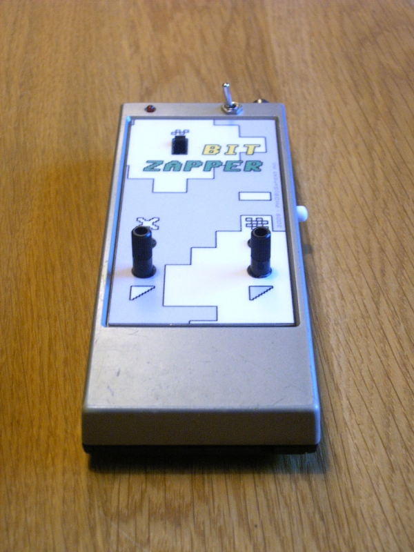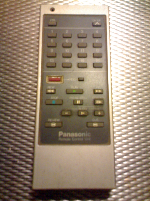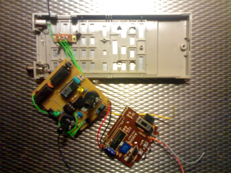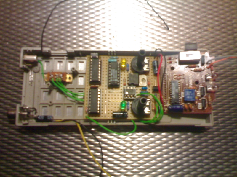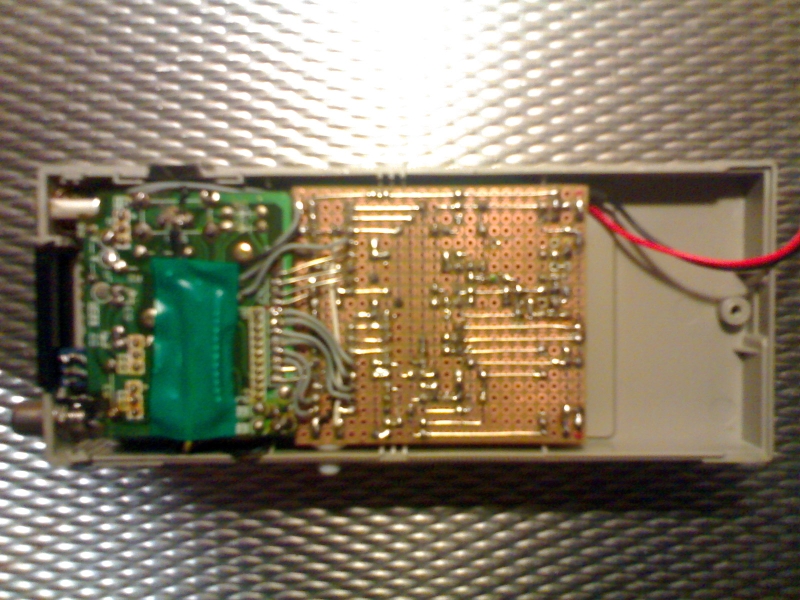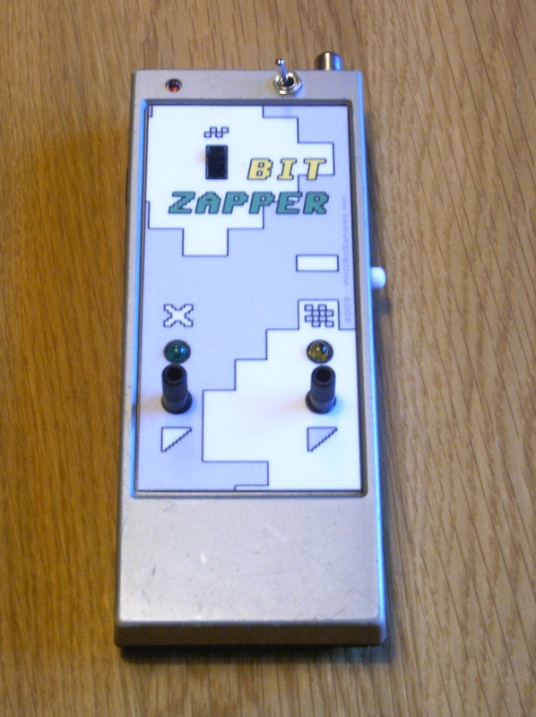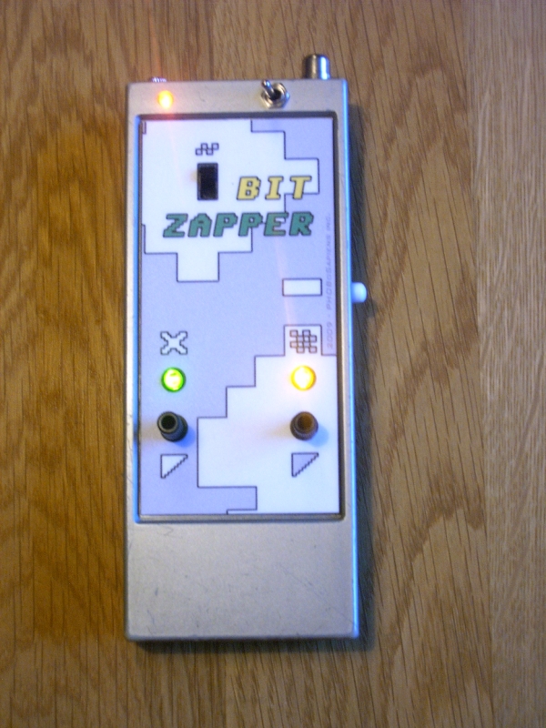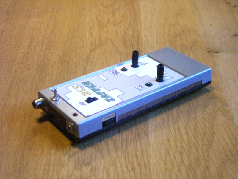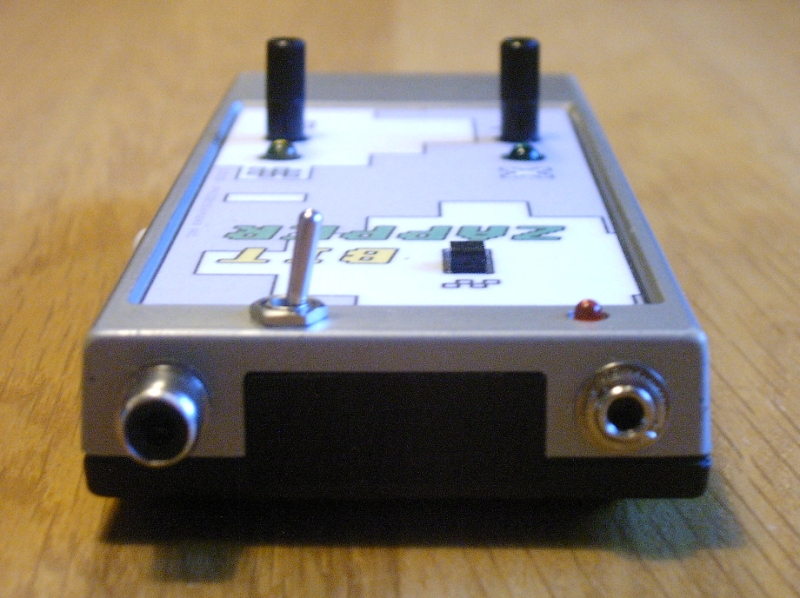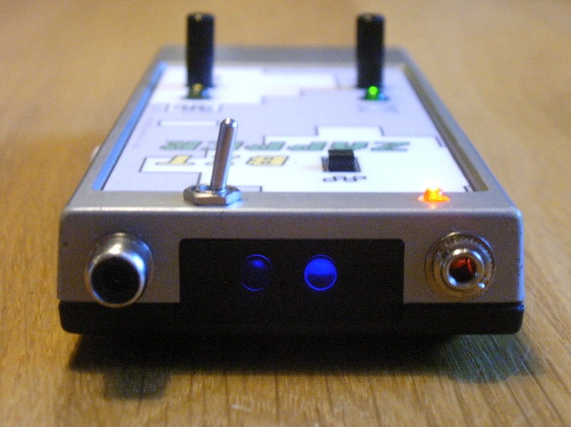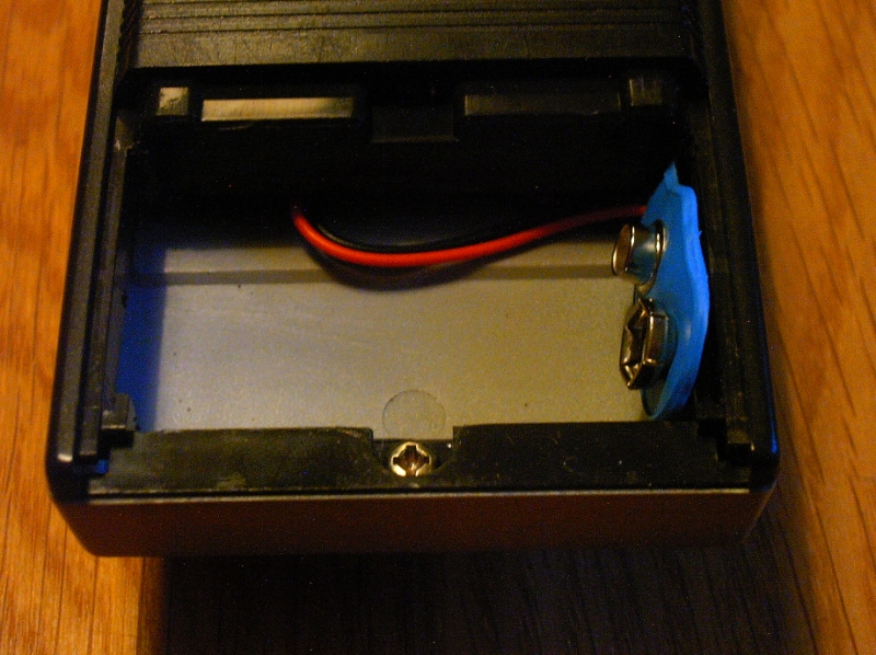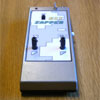
| After I had used a Light 2 Sound circuit to listen to a remote control, I thought to myself; 'I should probably get the same sound if I leave the light transmitting/receiving part out'. In other words, take the audio straight from the remote. I didn't want to hack my TV remote but luckily I also had 2 very old remotes which I bought a very loooong time ago (together with 2 receivers), so I decided to use those for my experiment. I opened one of them, connected a computer speaker to the Ir_LED's and started pushing the buttons. As I expected it worked perfect. I also tried the other remote, which had a slightly different sound to it. One of the remotes uses a ceramic resonator for the CLK speed of the chip, the other one a LC-circuit with an adjustable L. I tried different oscillators to change the speed (and thus the pitch of the sound) but wasn't successful. I also tried if I could find some bent points but there wasn't anything I could use. For this first remote control bent I choose the one with the ceramic resonator. It had 2 PCB's, 1 with the circuitry and 1 for the buttons, connected together with a small piece of flat cable. The buttons where wired in a 6x8 matrix with some combinations unused, so I tried shorting the unused combinations and they functioned just as the other buttons. The sounds the different buttons create are almost identical but if you listen closely you can hear a small difference. I used a binary counter (4060, which has an internal oscillator) in combination with two 8-channel analogue multiplexors (4051) to step trough all the different combinations of the 'button matrix'. Because it's only a 6x8 matrix it had 2 unused in/outputs on one of the muxes which would cause a silence when selected by the counter. So I connected those to another in/output and used a switch for one of the connections (the silver toggle switch). When this switch is closed you get a nonstop pattern and when it's open you get a pause every 8th step. I had noticed that just stepping trough all the combinations didn't work the way I expected. The remote needed a short pause between every step, else it would just keep repeating the first one. I could have used the first output stage of the binary counter to do this but using an extra oscillator makes it much more interesting. Basically the counter selects a button on the remote and the oscillator presses it down, so by setting different speeds for the oscillator and the counter I get different patterns. If I had used the first output stage of the binary counter it would have stepped trough all the combinations in the same pattern over and over again. But there's also another interesting effect. When you press a button on a remote control it sends out a code and keeps repeating this with a certain interval as long as the button is pressed. Now, when I set the oscillator to approximately the same speed as the remote uses to repeat the codes, the sound starts breaking up in a kind of rhythmical way. The oscillator can be turned off with a switch to silence the remote and I added a connector for an external oscillator which is selected when the internal oscillator is switched off. I also added a pushbutton (the white one on the side) for manual control. The remote worked on 3Volts using 2 AA-type batteries which was way too low to power the circuit. So I used a 9Volts battery instead and used a variable voltage regulator (LM317) to create the 3Volts necessary for the remote circuitry. To get the 9Volts battery in I had to cut out all the plastic that originally held the 2 AA-type batteries. To do this I used a small drill with a very small circular saw blade. I also used the drill together with a grinding bit to remove a part of the support structure on the inside of the remote (back side of the front, see third photo) to get just enough space for the print, it's really a tight fit! I wanted to replace the 2 Ir_LED's with 2 'normal' LED's but there's a small very dark, yet transparent, piece of plastic in front of the 2 LED's, I guess it's an Ir filter. so first I tried different LED's to see what the effect was in combination with the plastic. UV LED's turned out to work best but because of the low voltage I couldn't use them and I ended up with using either red or white. The red LED's gave a really dim red glow, but the (very bright!) white LED's had more of an UV light look to it which I liked better. The remote also had a red LED in the top left corner, that flashed when you pressed a button. This LED had a very small tip but the rest was the size of a flat 5mm LED. To get the connector for the external oscillator in I had to replace it. So I made the hole a bit larger and glued in a 3mm LED which almost doesn't take up any space on the inside of the remote. To get a smooth surface for the front, I removed the sticker with all the lettering and used a piece of thin aluminum to cover the holes. The font I used is 'commodore 64' because the sound reminded me of old video games. The sound is taken directly from the chip instead of the LED´s with a 1K resistor and a 10uF capacitor in series for protection. |