| I got inspired by a topic on synthforum.nl
about neon oscillators. I have used oscillating neon bulbs in the past to drive stroboscope lights but
never thought about using them at a high frequency for audio purposes. There are some schematics (1,2)
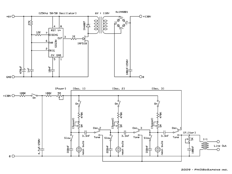
posted on the forum but the circuits are mains powered by a 230V->110V transformer and a rectifier circuit [130V=]
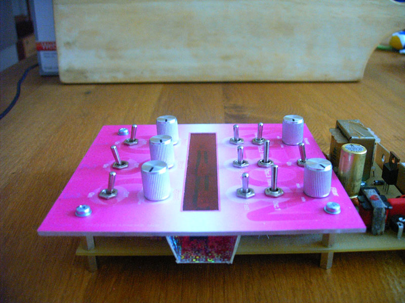
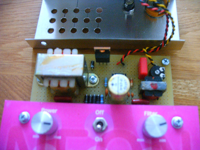
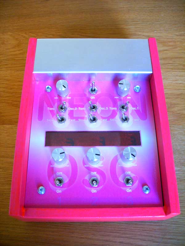
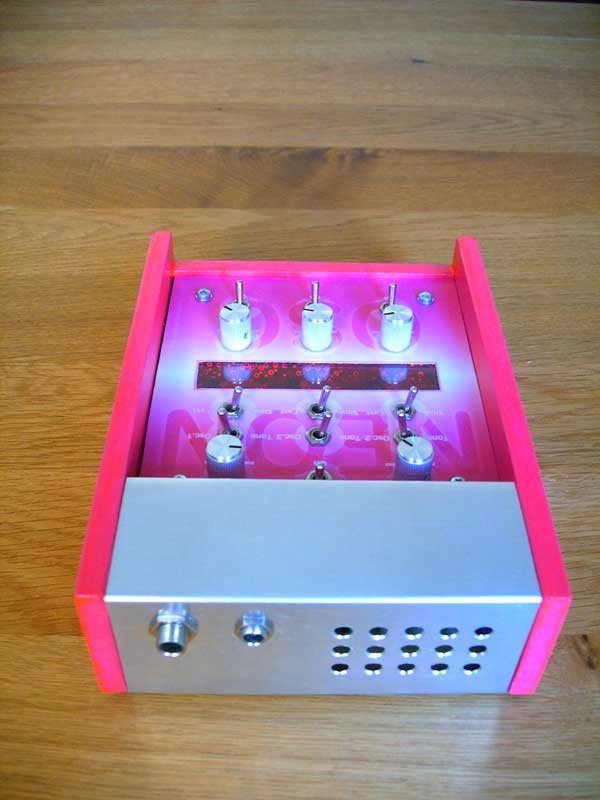
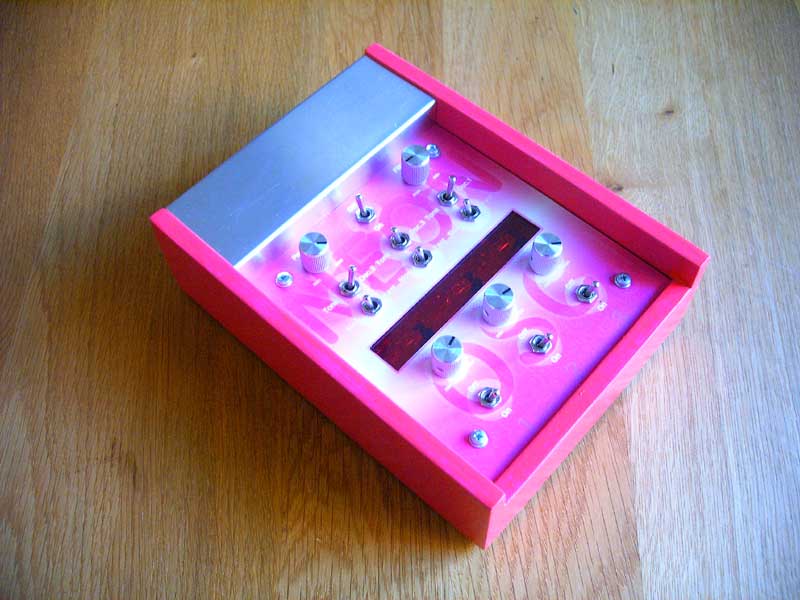
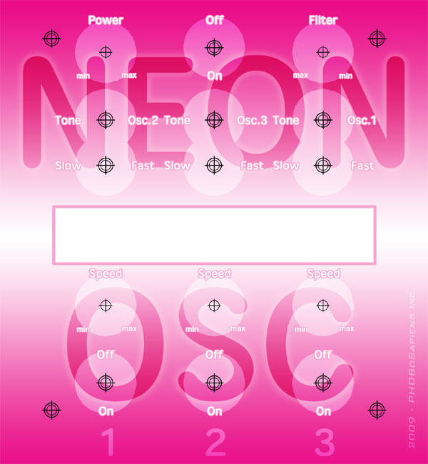
And even though I like an electric shock occasionally I didn't really felt save poking around on a breadboard with those voltages. I remembered using an 555-based oscillator (duty-cycle=50%) for driving a flyback transformer so I decided to try a normal transformer connected backwards (secondary winding as input). The transformer I used has 2 primary windings (110V) and 1 center tapped secondary winding (6V-0-6V). It's a small transformer and I think the maximum current is somewhere around a 100mA (if you use it the way it is supposed to). I build the circuit on a breadboard (Oscillator->transformer->rectifier+capacitor), crossed my fingers and applied 6V=. No explosions or smoke, so I measured the output voltage: exactly 130V! (but much more safe to touch!) I had 3 old neon bulbs laying around gathering dust so I connected one in series with a 100K resistor and it gave a nice orange glow. [The transformer and FET do get a little bit warm but it's an Ok warm, not the "I knew I shouldn't touch that!", burning you're fingertips hot] Next I build one oscillator and connected a small transformer, that looked like it could be an audio transformer, to a computer speaker (great for testing audio circuits). I got a high pitched buzzing sound but had to turn the volume up pretty high. I build a second an third oscillator tried different capacitors and got some nice sounds, but I had to wire the audio outputs differently then in the circuits posted on the forum to get sound from all of them (maybe this has something to do with the high voltage circuit I use?). The sound was still not really loud and since I didn't trust the transformer I was using I searched for a better one and found a real audio transformer. It was a bit broken and I had to use some superglue to fix it but it worked great. The sound was much louder and had more body to it. I did some more experimenting, put in a very basic filter and after a while I a had a nice beeping/buzzing circuit. I designed a print-layout and build it on a eurocard sized perf-board, which turned out to be a lot more work then I had thought it would be because I had to glue all the switches to the board. The first time I powered it up it didn't work, so I looked closely and immediately turned of the power when I noticed I had connected it the wrong way! followed by a "I knew I shouldn't touch that! (FET didn't like wrong power). I usually put in a safety diode to avoid this but that would drop the input voltage, and since the circuit can be battery powered that seemed like a waste of power. I replaced the NE555 and connected the power with great care for a second try. First few seconds nothing happened (charging the 4.7uF cap) but then it started blinking. I hooked up the speaker and it almost worked perfect except for one bulb that seemed to have some problems and once in a while turned into a blue plasma-bulb. I had already ordered some new neon bulbs to do some more experimenting (maybe a flashy chaser) so when they arrived I replaced all the old ones. The difference was pretty amazing, the old bulbs sometimes stopped oscillating at high frequencies but the knew ones keep on going. My first plan was to mount the print on a piece of wood with a small piece of aluminum at the back for the connectors and leave it like that. But I decided to put sides on it as well to make it easier to mount the back and make it less vulnerable. Next came the idea of putting a plexiglas cover on it and the aluminum back turned into a cover for the transformer. I had an old can of neon pink paint (UV reactive!) which seemed like a logical choice, so with this color in mind I started designing a front cover. I added a piece of a red plastic (light filter) to the backside of the front cover and a small reflector made of cardboard with some sort of shiny holographic print on it. And finally I added some nice small metal knobs (most expensive parts of the oscillator). I'm pretty happy with the final result, though the paint job isn't really smooth which is clearly visible under UV light, but that's OK. |