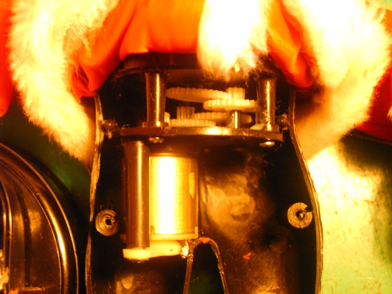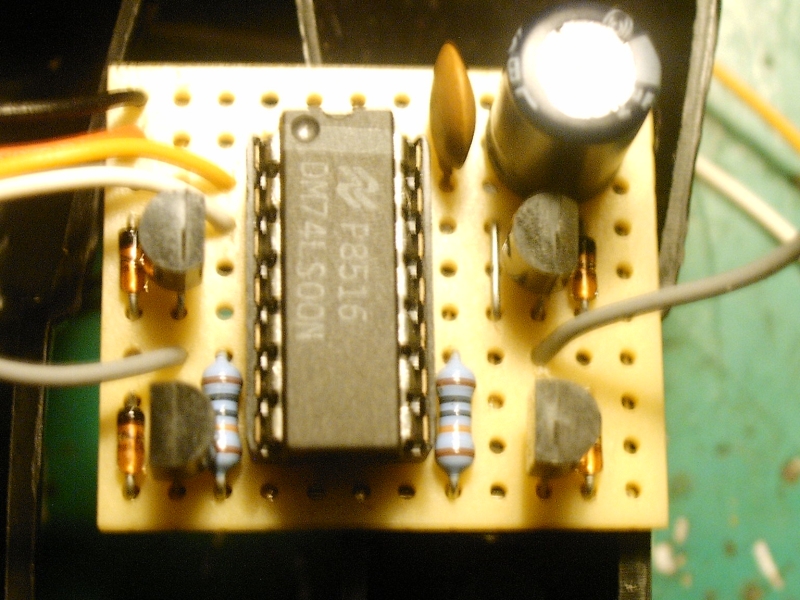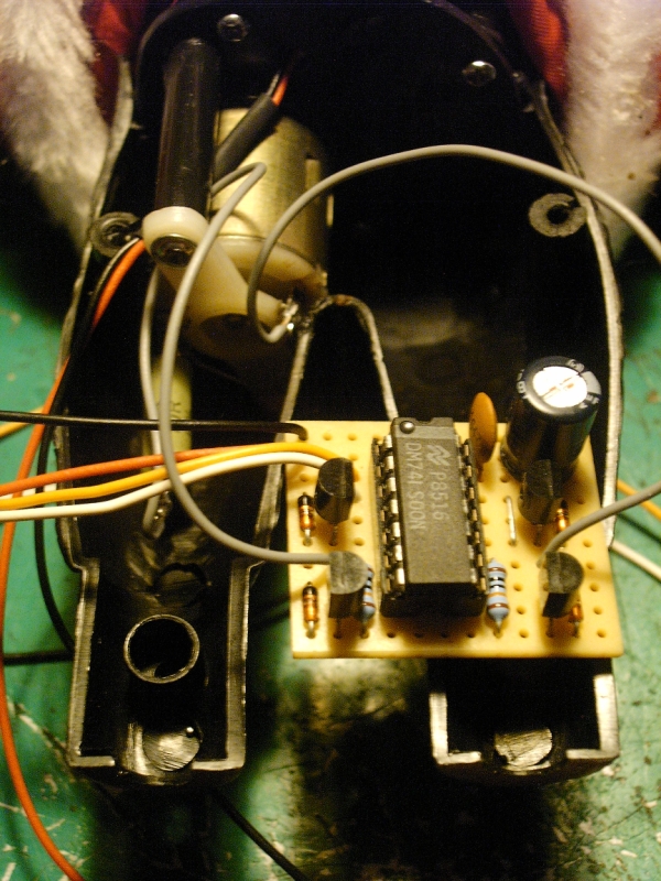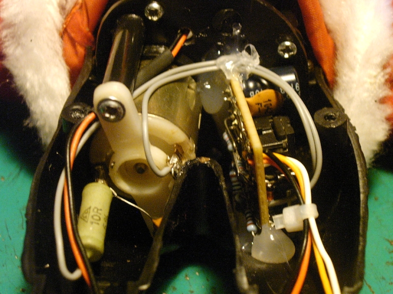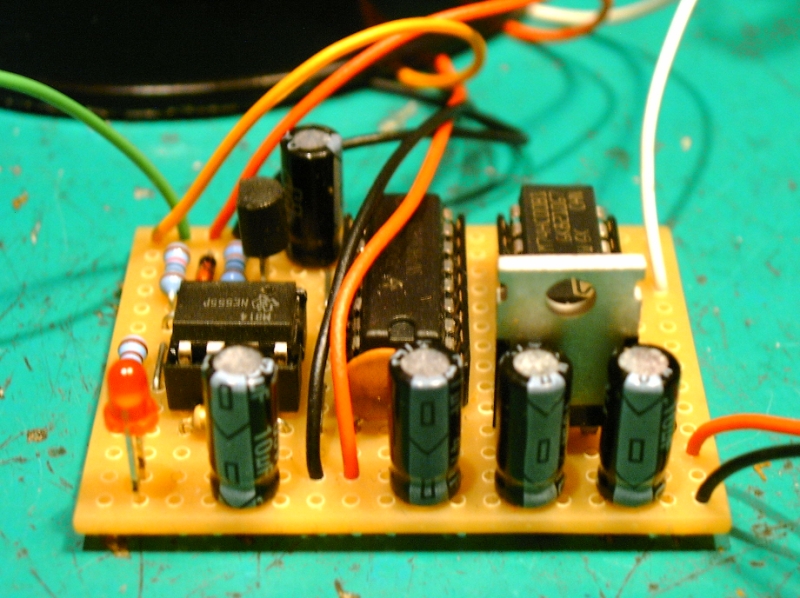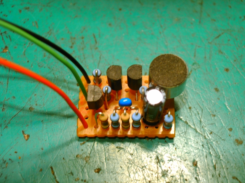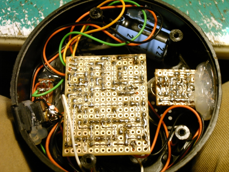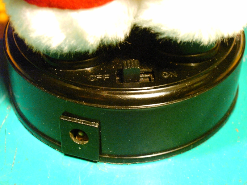
| Something special I did for the holidays (X-MAS '09). Originally Santa just kept moving in one direction accompanied by a very annoying jingle bells melody. I wanted to make him move to the beat so I needed to be able to reverse the power to the motor. To do this I needed an H-bridge. To make the control of the H-bridge a bit easier and prevent shorting the transistors I designed a small circuit with 4 NAND gates. This circuit reduces the control lines from 4 to 2; one for the direction of the motor [DIR] and the other one to turn the motor on/off [E]. I usually use CMOS logic but I wanted the circuit to work with 5 Volts so I could just put a resistor in series with the motor without it getting too hot. (the motor turned fast enough on 3 Volts and I didn't want to use PWM). So this time I used a TTL chip. I only simulated the NAND circuit and after I had soldered everything together it didn't work. I did some tests and it turned out I forgot to use pull-up resistors and I also needed resistors between the base of the NPN transistors and the NAND gates. Because there wasn't enough space left on the board I soldered them on the bottom side. Next up was the 'Dance Decoder'. My initial idea was to use an audio controlled flip flop to change the direction of the motor. There are a lot of different ways to do this but to keep the number of components to a minimum I used a 12-Stage binary ripple counter (74HC4040). Because I now had 11 additional outputs I decided to use them to give Santa some more fancy moves. To do this I used 4 extra NAND gates (74HC00). I also made a timer with a 555 which turns the motor off after a few seconds if the audio level is to low. Because I wanted Santa to react to the music I needed a circuit that turns an audio signal into a nice pulse. I've successfully used this circuit before and it's the best one I've seen so far. But I couldn't get it to work this time because of the noise on the power line created by the motor. So I needed something else and just in time I discovered a very simple circuit from a 'dancing flower' on this great site. And with some small adjustments is worked perfect. Of course I also had to do something with the candle Santa is holding. So I replaced the original light bulb with an autofading RGB LED, also controlled by the 'dancing flower' circuit. Because I soldered a capacitor parallel to the LED and put a diode in series with it the fading circuit inside the LED continues for a few seconds after the power to the LED is gone. This way the LED flashes in different colours. One more thing I did was to rewire the original On/Off switch so it functions as a mode switch. You can choose between audio and normal mode. In normal mode Santa keeps moving in one direction and the candle fades trough all the colors. I also had to put in an additional buffer elco because of the noisy power supply I use.  During the build of this project I got a nice surprise. In the description of the 'white rabbit piano' I joked about the blobs always being black. Well, this time the PCB that produced the annoying jingle bells melody had a GREEN! blob. I still have to take a picture of it and I think I'm gonna do something special with it, but that's something for another X-MAS. Ho Ho Ho,.. During the build of this project I got a nice surprise. In the description of the 'white rabbit piano' I joked about the blobs always being black. Well, this time the PCB that produced the annoying jingle bells melody had a GREEN! blob. I still have to take a picture of it and I think I'm gonna do something special with it, but that's something for another X-MAS. Ho Ho Ho,.. |